|
|
|
|
Video Text Overlay Unit with PC keyboard interface,
|
|
Real Time Clock & On Screen Counter
|
|
|
| The RTCKBDBOX unit allows a PC keyboard to be used to create video text overlays
to annotate a video picture. They are designed for general purpose video inspection tasks. A board only option
is also available. |
|
|
The RTCKBDBOX unit is housed in an anodised aluminium enclosure. Phono video connectors
are supplied as the default. BNC connectors are available as an option on request. Power is supplied via a 2.1mm
DC power socket. The unit is designed to be powered from the same 9 - 12V power supply as the camera. It has a
power switch to enable it to be isolated for use in battery powered systems. Keyboard connection is via a USB socket
for a PC keyboard. These units will only work with standard USB PC keyboards. The character size cannot be changed
by the user, although some customisation of the character set is possible, please see below. Please contact us
before you make your order for details of customisation or if you have any other questions. |
|

|
|
| PC keyboards use two types of signals: HID and PS/2. Many wired USB keyboards will
support both types of signals, defaulting to HID, but switching to PS/2 when connected to a device that does not
support HID signals. However some wired, and all wireless, USB keyboards are HID only. The RTCKBDBOX unit and RTCKBD-USB
boards are only compatible with HID USB keyboards. Only order the RTCKBD board if you intend building a system
with a PS/2 keyboard connector or will use a USB keyboard that you know has PS/2 functionality. |
|
|
|
 |
|
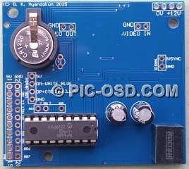
Board only option
|
|
|
|
 |
|
Board only option
|
|
|
To use the board only options you will need to make connections
as described on the following pages.
|
|
RTCKBD-USB overlay board connections
page
|
RTCKBD overlay board connections
page
|
|
|
|

|
| A keyboard is not included. Order the FLEXKYBD item for use with these units. |
|
|
|
| For full details of the unit's operation please see the documentation. |
|
|
|
|
|
|
|
|

|
|
The unit has eight pages of text which can be edited seperately
|
|
|
|

|
|
The clock and counter display can be placed either at the top or
bottom of the screen.
|
|
|

|
| The RTCKBDBOX unit has a 3.5mm jack socket for connecting an external rotary encoder
or other circuit to provide the input to the on screen count. Logic levels are 0 - 5V TTL. A 3.5mm jack plug is
supplied with the unit as illustrated below. The counter display increments / decrements by 1 between +99999 and
-99999. The encoder count is basically displayed as a number without units for flexibility in different applications.
It could represent depth / distance in metres or feet for example as required. |
|

|
Please note that the counter is not a direct distance measurement. You will need to know the counts per turn and turns per
unit of distance measurement given by the encoder used in your system to read the display. There is the facility
to set up a pre-scaler for the count using the keyboard. A prescale constant between 1 and 2048 can be set to allow
the counter display to be adjusted to match the external count source. |
|
| Essentially if you had a 500 count per turn encoder you would set the pre-scaler
to 500 and each turn would advance the count displayed by 1. This would count the number of turns. If you had 3
turns per metre then you could set the pre-scaler to 1500 and each count increment on screen would represent 1
metre. Set the pre-scaler to 150 and each count would represent 10cm, and so on. The position of the decimal point
in the count display can be changed to one of five positions. The decimal point can be placed to reflect the counts
per whole number. |
|
|

|
| The counter can be hidden if not required. The position of the decimal point in the
counter display can be changed to one of five positions to allow the count to represent fractional distances. |
|
|

|
| The counter can be reset either from the keyboard or from the reset button on the
unit. A reset preset constant can be set from the keyboard. By default this is zero, but any other counter value
can be set as the value the counter will be reset to. The counter value is preserved when power is removed from
the unit. |
The direction pin is pulled high internally to give a positive count by default if left unconnected. When used
with a incremental rotary encoder connect channel A to counter and channel B to direction as shown below. For details
please see the RTCKBD overlay board
connections page. |
|

|
|

|
|
| Counter Pin |
0 - 5V TTL, count on the rising edge |
| Direction Pin |
5V TTL logic high for + count, 0V TTL logic low for - count |
| Ground |
Common Ground |
|
|
|
| Features |
 |
Eight separate text pages 26 x14 characters PAL, 26 x 11 rows NTSC. Font and character
size fixed. |
|
24 hour format Real Time Clock |
|
UK English or US International keyboard mapping available. |
|
Compatible with colour and mono composite video signals. 1Vp-p. PAL or NTSC |
|
RTCKBDBOX dimensions 95 x 108 x 34mm LxWxH |
|
RTCKBD dimensions 60 x 54 x 20mm LxWxH |
|
Power supply required 9 - 12V DC |
|
Power consumption 50mA (without keyboard) |
|
Operating Temp. 0° - 85°C |
|
|
|
 |
The RTCKBDBOX unit can be used in a wide variety of systems and no one power supply
solution would be suitable for them all. Therefore the unit does not include a power supply as standard. You may
already have a suitable power supply or you may wish to source this requirement locally. Otherwise UK customers
should order the PWRSUP item. This item is not available to customers
outside the UK. |
|
|
|
| Mounting Brackets for RTCKBDBOX units. |
 |
|
|
| BNC CONNECTORS |
| The RTCKBDBOX units can be supplied with BNC connectors on request. If you want this
option then make your order in the normal way, then just email us quoting your order number: sales@pic-osd.com |
 |
|
|
Alternate firmware
|
|
RTCKBD-S firmware for text scrolling
|
|

|
| The standard RTCKBDBOX firmware does not allow text scrolling. For applications such
as ATV repeaters that require this functionality please contact us and request the RTCKBD-S firmware. |
|
|
RTCKBDBOX-CU timer firmware
|
|

|
| The RTCKBDBOX-CU firmware replaces the external counter interface with an on screen
timer which can be set with a user defined period. For more details please see the documentation. Email us to request this option
when you make your order for the RTCKBDBOX unit or the RTCKBD board. |
|
|
| Alternate Character Sets |
| At the time you make your order we can provide one of two alternate character sets
to the default standard character set. The character set cannot be changed by the user once units are delivered.
The standard character set is suitable for a wide range of applications including those where small screens are
used or viewed at a distance. The smaller alternate character sets can be more suitable for use with LCD panel
displays. For other details please see our characterset
customisation page. If you want either alternate character set then make
your order in the normal way, then just email us quoting your order number: sales@pic-osd.com |
 |
| Alternative character sets for languages such as French, Danish or German, shown
below, can be provided. For other languages please contact us before you make your order: sales@pic-osd.com |
 |
|
|
|
|
|
|
|
© The BlackBoxCameraTM Company Limited
2025
|
|


