|
|

|
|
RTCKBD-USB Video Overlay
Board Connections
|
|
| This page gives instructions for the connection of the RTCKBD-USB video overlay board
to keyboard, counter, power, video in and video out. |
|
|
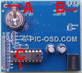
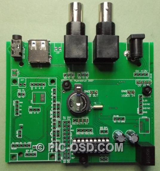
Power and Video Connections
|
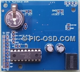
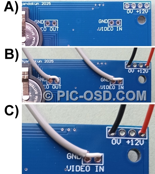
The positions for the connection of power, video in and video out are clearly marked
on the video overlay board shown in insert A below right. A 9 - 12V DC regulated power supply should be connected
to the points marked +12V and 0V as shown in inserts B and C, close up, below right. Care should obviously be taken
in connecting the power supply. Although the designated power connection points are protected against accidental
reverse polarity connection, connecting the power elsewhere on the board will result in its failure. Our warranty
specifically excludes failure due to improper connections. Please ensure that all soldering or other connection
work is done in accordance with these instructions.
The video connections shown in this example are made with screened coaxial cable suitable for video signals. The
lapped screen which carries the video ground from the camera is connected to the video ground on the board. Care
should be taken to ensure that the video grounds and power ground are connected separately. |
|
|
|
|
|
5V Power Connections
|
| The 9 - 12V DC regulated power supply is reduced to 5V DC by the 500mA switch mode
regulator on the video overlay board. This 5V output is available to power a PC keyboard or user designed circuit.
The connection point for the 5V output is shown in the highlighted insert below left, marked 5V. WARNING: There is no polarity protection on
the 5V output. Short circuiting this point on the board to ground, either directly or via the attached circuit,
will damage or destroy the video overlay circuit. The warranty is void in such cases. The board may also be powered
from an external circuit with a 5V power supply connected to this point. |
|
|
|
RTCKBD-USB Keyboard Connections
|
|
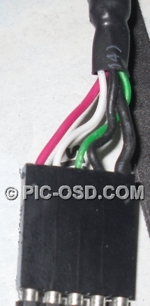
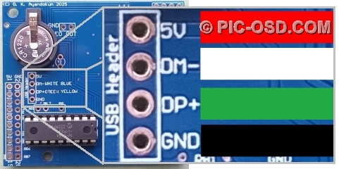
The RTCKBD-USB video overlay board has a standard pin out 4-pin
USB connector as shown below.
|
|
|
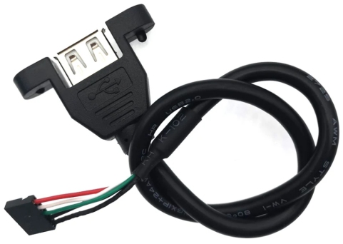
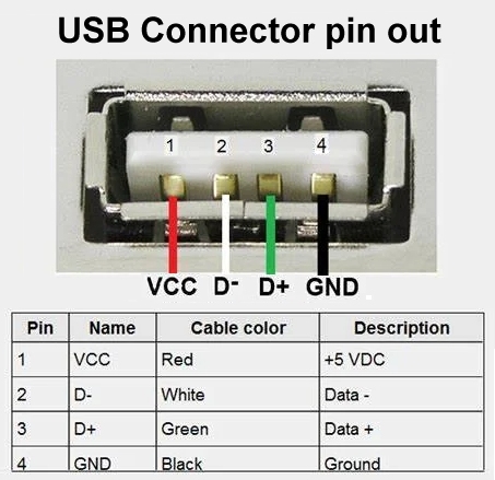
| This connector allows the wired connection of a standard USB A keyboard socket with
the standard pin out and wiring colours as shown below. |
|
|
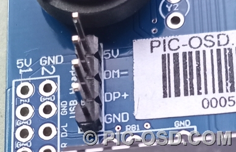
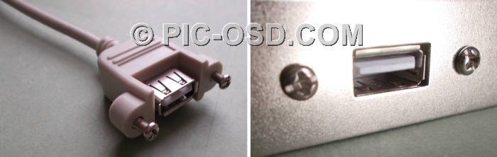
| As an alternative to a wired connection a 2.54mm pitch four pin jumper (not supplied)
can be installed on the RTCKBD-USB board as shown below. This allows the use of a wide range of industry standard
USB A sockets designed for panel mounting. These panel mount connectors typically have a standard 5 pin socket,
however pin 5 is normally the cable shield and can be left unconnected. |
|
|
|
|
|
No panel mount USB connector is supplied with the RTCKBD-USB
board.
|
|
|
|
|
|
RTCKBD-USB - Counter Connections
|
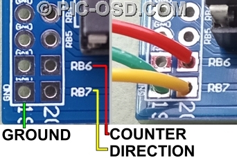
| The on screen counter is driven by a TTL rising edge on RB6 as shown below. The direction
of the count is determined by the state of RB7. If the RB7 pin is TTL high then the count is positive. If it is
TTL low then the count is negative. The counter increments / decrements by 1 between +99999 and -99999. Please
note that the counter is not
a direct distance measurement. You will need to know the counts per turn and turns per distance measurement given
by the encoder used to read the display. A prescale constant between 1 and 2048 can be set to allow the counter
display to be adjusted to match the external count source. The position of the decimal point in the count display
can be changed to one of four positions. The direction pin is pulled high internally to give a positive count by
default if left unconnected. When used with an incremental rotary encoder connect channel A to RB6 and channel
B to RB7 as shown. |
|
|

|
|
|
| Counter Pin |
RB6 |
0 - 5V TTL, count on the rising edge |
| Direction Pin |
RB7 |
5V TTL logic high for + count, 0V TTL logic low for - count |
| Ground |
GND |
Common Ground |
|
|
|

|
|
|
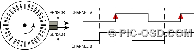
Anti-clockwise rotation - positive count
|
|
|
| When the encoder is rotated anti-clockwise, each rising edge of channel A occurs
when channel B is high. This gives a positive count. |
|
|
|
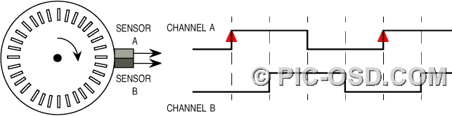
Clockwise rotation - negative count
|
|
|
| When the encoder is rotated clockwise, each rising edge of channel A occurs when
channel B is low. This gives a negative count. |
|
|
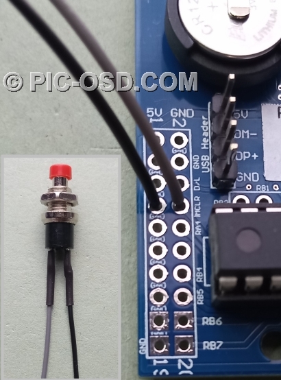
Counter Reset Connections
|
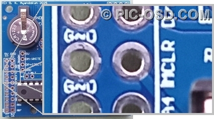
| The counter can be reset either from the keyboard or from a reset button connected
to the board. This should be a momentary push button connected between !MCLR and GND as shown below. The counter
value is preserved when power is removed from the unit. |
|
|
|
|
|
|
Mounting Holes
|
| RTCKBD-USB 3mm mounting hole positions, coordinates in mm relative to bottom left corner
of the board. |
|
 |
| Mount Hole |
X |
Y |
| A |
3.50 |
50.50 |
| B |
56.19 |
46.76 |
| C |
14.46 |
3.14 |
|
|
| Coordinates for connection points can be provided on request to customers who wish
to integrate the RTCKBD board onto their own custom carrier pcb. |
|
|
|
|
|
|
|
|
|
© The BlackBoxCameraTM Company Limited
2025
|
|